SDI-12 Information
See the SDI-12 Spec for complete descriptions of the communications protocol.
Data Logger
SNOdar was developed against a CR1000X Campbell Scientific Data Logger.
- The program 1_minute_9_values.CR1X was downloaded to the CR1000x data logger to log from the SNOdar using SDI-12.
- The program 1_minute_9_values.cr6 was downloaded to the CR6 data logger to log from the SNOdar using SDI-12.
Both programs include variable names and units. They were created with the Short Cut program.
Data
The 9 values supplied over SDI-12 by the SNOdar, in order, are as follows:
// Sensor Data
1. System Current (mA)
2. System Voltage (V)
3. Internal Temperature (degC)
4. Orientation Flag (0 = normal, roll = bit 2, pitch = bit 1, yaw = bit 0)
5. Distance (meters/inches)

// DSP Data
6. Seasonal Snow Depth (meters/inches)
7. Seasonal Snowfall   (meters/inches)
8. Daily New Snowfall  (meters/inches)
9. Day-of-Year SWE     (meters/inches)
Commands
SNOdar is sensitive to three standard SDI-12 Commands issued to SDI-12 address 0. The supplied CR1X/cr6 programs tell the data logger to use these three SDI-12 commands to extract data from the SNOdar.
- Acknowledge Active:
0! - Send Identification:
0I! - Start Measurement:
0M!
Acknowledge Active
To query if the sensor is active and responsive, use the following command and format:
<a>!
Where:
a: sensor address, e.g. 0
!: terminates the command
A typical response would be the sensor address followed by the termination response:
a<CR><LF>
Send Identification
To query the sensor identification, use the following command and formatg (as of FW v0.8.6):
<a>I!
Where:
a: sensor address, e.g. 0
I: identification command
!: terminates the command
A typical response may look like the following:
014SENLOGICSNODAR0862P0
Where:
0        = sensor address
14       = SDI-12 compatibility number
SENLOGIC = company name
SNODAR   = sensor model number
086      = firmware version
2P0      = hardware version
Start Measurement (sensor address 0)
0M!
followed by Send Data Commands.
0D<n>!
Where:
n: Increasing integer value starting with 0. Send Data Command is issued until all 9 pieces of ASCII data are received.
The above mentioned 9 pieces of ASCII data will be returned on the SDI-12 line. The data will come back in multiple responses to incrementing Send Data Commands. The values are broken up into 35 max character responses, where individuals records are not split between responses.
If the sensor is set up in Manual mode, the SDI-12 data logger actually initiates a measurement using the following command:
0M!
This will return a time delay, in seconds, that the logger needs to wait to then request the data using Send Data Commands:
0D<n>!
Wired Connection
| SNOdar Pin Name | SNOdar Pin NO. | Cable Pin NO. | Wire Color |
|---|---|---|---|
| GND | 1 | 1 | BLACK |
| +12-24 VDC | 2 | 2 | WHITE |
| GND | 3 | 3 | GREEN |
| SDI-12 | 4 | 4 | RED (yes, this is correct) |
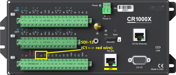
- Connection diagram for the CR1000X

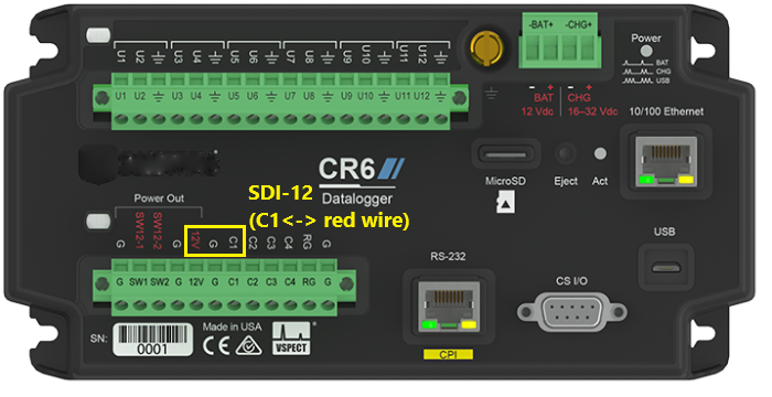
- Connection diagram for the CR6
